2019 Offseason Contributions
Complex Mechanical Subassemblies
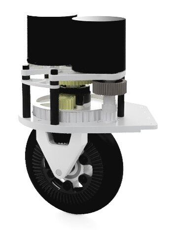
I designed a two-speed custom gearbox that positioned the motors over the tubes of the drivetrain to save space in the center of the butterfly drive. This design required learning a lot about gears and gear ratios, the fundamentals of drive systems, as well as tolerances in machining. The gear ratios for this gearbox were optimized using an excel spreadsheet that could find the theoretical ground speed of the robot given weight, gear ratios, wheel diameter, etc. I then generated CAM using Fusion 360’s integrated manufacturing workspace and machined all of the plates on a Laguna 4’x4’ CNC router.
Swerve Drive
Team 2910’s “SDS Mk.2” swerve module
After the 2019 season, the team set a goal to have a functional swerve design by the 2020 season. Swerve drives are considered the most maneuverable and complex FRC drivetrain, consisting of four independently steering and driving modules at each corner of the robot. A robot with a swerve drive is capable of strafing and rotating in any direction or orientation without sacrificing traction. Given the complexity, we decided to modify an existing, proven design at first rather than developing our own from scratch. We modified team 2910’s “SDS Mk.2” swerve design to include custom 5” pneumatic wheels and machined four modules completely in house. Here is where I learned how to generate CAM for and operate a small Tormach CNC mill. This made our swerve drive one of a few in the world to feature pneumatic wheels which offered great traction, better wear properties, and the capability to traverse floor obstacles much quicker than the traditional 4” treaded wheels.
Our custom pneumatic swerve module
Drive Train Simulator
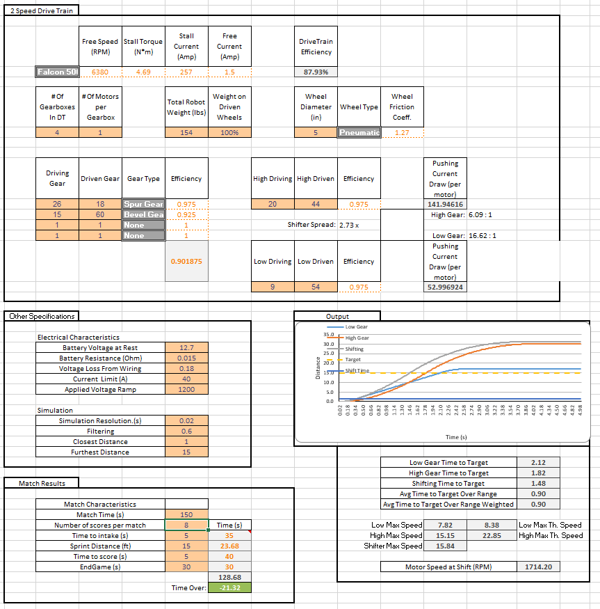
I wanted to learn Excel in my free time so I decided to make an improved version of the aforementioned excel spreadsheet used to calculate the theoretical ground speed of an FRC Robot. I wanted to create a similar tool that would take into consideration more variables (like rolling friction and efficiency losses), simulate the acceleration of the robot to find a time to target, and support two-speed drive trains.
Pictured is the front end, where robot characteristics are specified and critical information is outputted. The primary purpose of this tool is to optimize gear ratios and compare the relative speeds of different robot configurations. We’ve used this spreadsheet every year since to help inform our choice of drivetrain. During the 2021 season I added the option for a range of target distances to be inputted with specified weights representing the expected number of times that distance would be travelled. I used Excel’s Visual Basic backend to automatically simulate the different sprints and store the results before averaging them and outputting a final result.
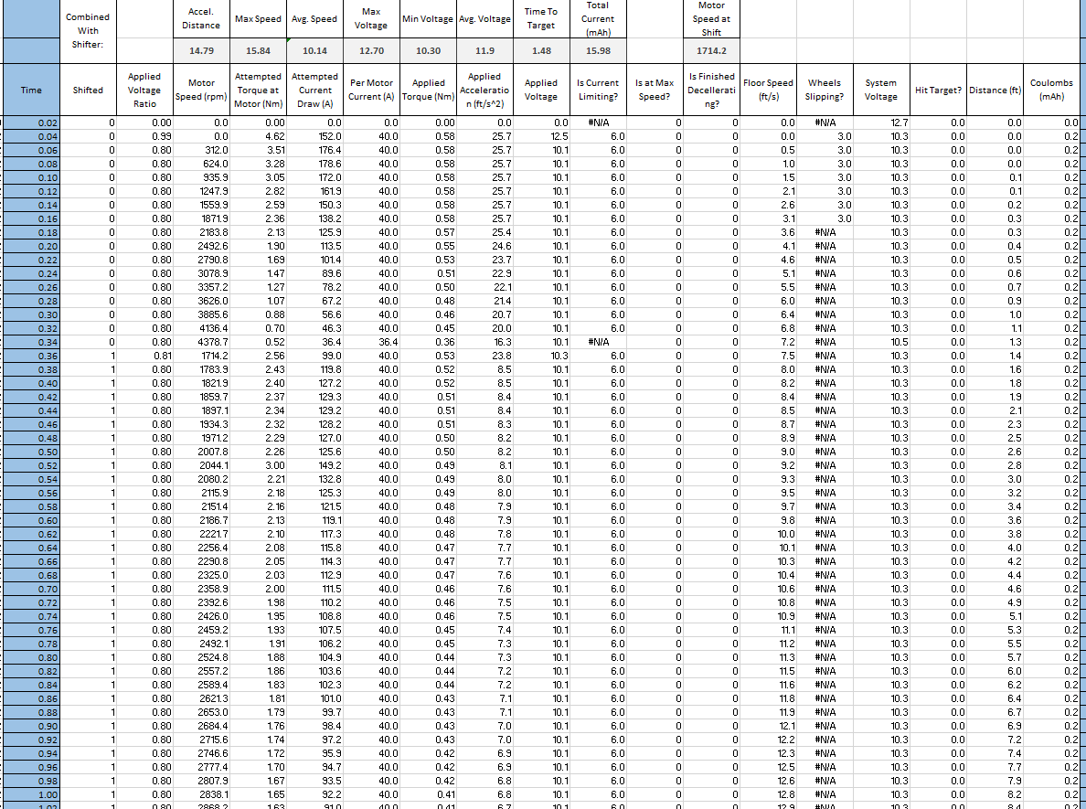
The complexity of this tool can be seen in the backend. The simulator works in three stages, one of which is shown here. First the robot in low gear is fully simulated, then the robot in high gear is fully simulated, and finally the third stage (1 second of which is shown) finds the best time and motor RPM to shift at in order to maximize acceleration. Each column uses an equation iterated over each time step to simulate the behavior of the robot. The output is the time it will take the robot to accelerate and drive a specified distance and the optimal motor RPM for the robot to shift at, which could then be integrated in our controls system allowing the robot to automatically shift at the optimal time without driver input.


