My Take on a Personal Electric Vehicle
During the 2020 FRC season I realized the value of approaching problems blind to its common solutions. Although not always practical, this approach allowed me to practice design in the context of an unsolved problem and often had two outcomes. Frequently, I would land on the same solution others had previously which gave me confidence in my process. Alternatively, I would wind up with something very unique. This project is an example of the latter.
Unfolded board (yes that is a render)
Design Breakdown:
Folding and semi-automatic lockout mechanism
Motor driven steering assembly
Drive
Battery and electronics integration
1.Folding and Lockout
Two hinges on the deck allow the board to fold while sliders that automatically extend when the board is opened interface with posts in the aluminum extrusion to lock out and prevent the board from folding while riding. These sliders can also be manually extended while the board is folded to act as an extendable handle.
2. Steering
A brushless motor controlled by an ODrive Pro running PID absolute position control with external encoder feedback drives a lead screw which pulls 4 lengths of dyneema rope to actuate the steering. The lead screw nut and back pulleys are allowed to rotate 15 degrees in either direction, the maximum tilt of the board, such that the steering position will not be effected by the tilt of the board.
3. Drive
A 4400W brushless motor is driven by a VESC motor controller. This motor drives a shaft that then drives both back wheels.
4. Battery and Electronics
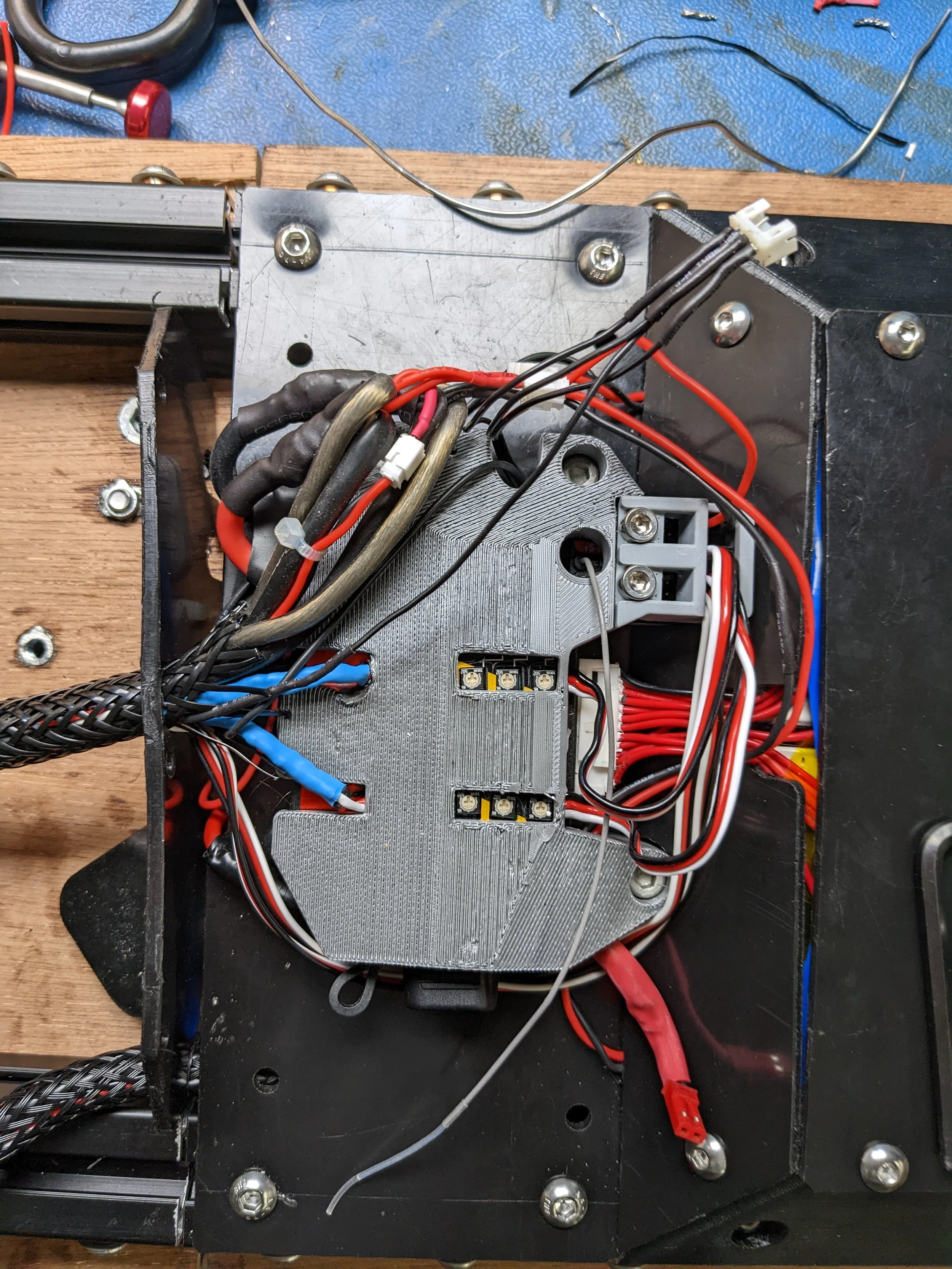
A custom 12s3p battery utilizing 21700 Molicel P42A cells gives the board a nominal 44.4v and 12600 mAhs of capacity. I spot welded nickel terminals onto the parallel groups and then made the series connections by soldering pairs of 12 AWG wire to the terminals. Also shown is the integrated balance charger, anti-spark switch, servo extenders (for 5 turn tilt limiting servos) and receiver, all of which are integrated into the back paneling of the board. Not visible are 2 DC-DC step down buck converters integrated into the 3D printed sides of the battery compartments creating 12v to drive the taillight LEDs and 8.4v to charge the custom controller that will mount and charge on the back of the board.
“Progress”
This video demonstrates both the drive and steering subsystems working together to drive the board around remotely. This video also shows a huge engineering oversight I had. I assumed both lengths of AMSTEEL that actuate the steering knuckles would be in perfect tension. This not being the case, the force of the steering mechanism resulted in a huge moment acting on the weakest part of the board, easily snapping the plywood. In the video I believe the failure happened while driving and resulted in the crash and not the other way around as I was being pretty light on the steering. Thankfully it should not be too difficult to brace the connection between the steering assembly and front “truck” with standoffs to eliminate any moments acting on the deck and machine the deck out of something more resilient to internal stresses… I’m thinking an impact resistant polycarbonate.
Lots of Iteration and Improvements…
Following the above failure, I realized I needed to change the way I was thinking about the load paths and overall design of the board. Rather than relying on the deck to provide support to the front and back, the undercarriage should be designed to withstand the necessary forces sans-deck entirely. The result was a lot of iterating making a bunch of small parts and improvements to the rigidity of the board. Here are some of the resulting fun parts (All machined on 3-Axis).
And here it is fully assembled, now with the aforementioned impact resistant polycarb. It does flex a bit, but not enough to be a problem, and it’s hard to complain about a bit of in-build suspension.
And without the deck on, because that’s where the good stuff is. For those wondering the back portion only half assembled here, hence why it’s not perfectly rigid.


